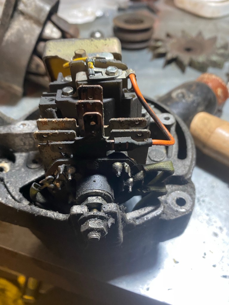
After managing to extract the steering relay from the chassis sometime ago it was time to give it the TLC it deserved to keep it going strong and avoid the shame of being replaced by a pattern part.
With due reference to the Green Bible it came apart pretty easily although the ancient oil was very thin, very black and plentiful. It left the place smelling like Bovington tank museum for days.
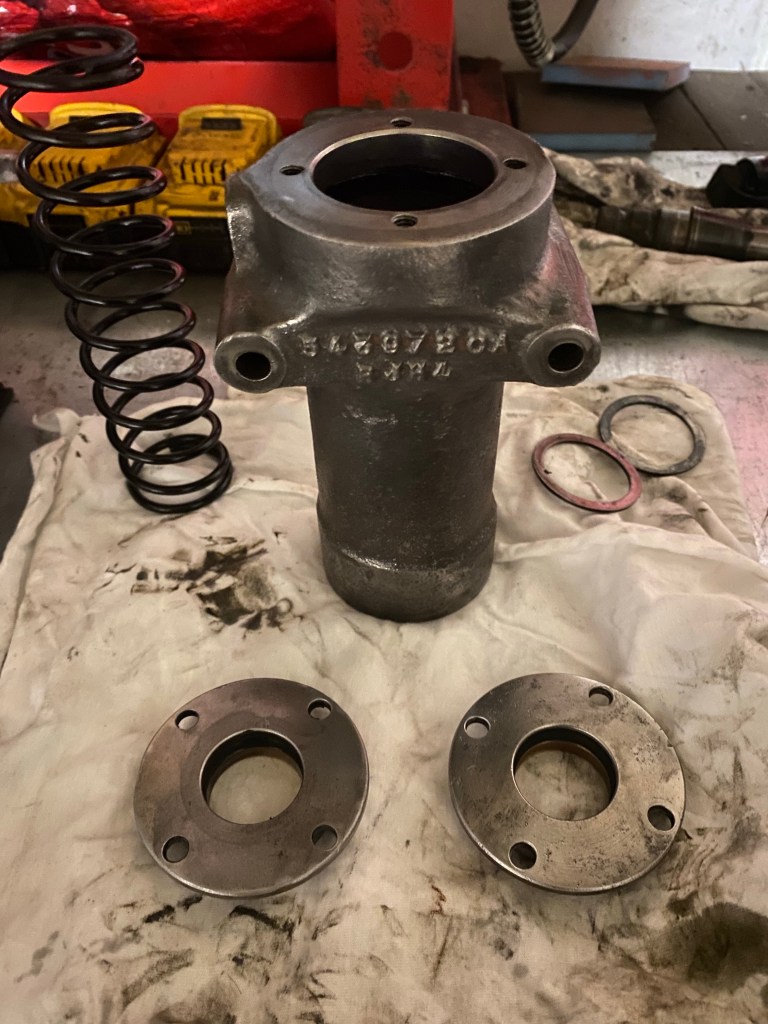
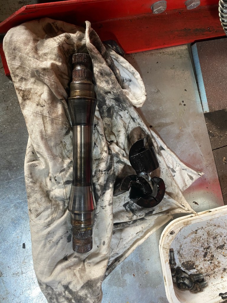
It a wonderfully efficient design with the spring energised taper bushes, but it does rather rely upon one pretty simple seal at the bottom to keep the oil in. This in turn relies on the shaft to be in top form. It gets a lot of abuse and so it wasn’t surprising there was a worn groove in the shaft. I decided to replace the shaft as I had found a NOS one but I suppose this one could have been turned the other way up, although that may have let water in.
Bushes are a readily available service item and the Green Bible gives a minimum length for the spring, which mine was just under. These are also easily obtained. I reckon if someone got a decent quality shaft made they could do a good job of refurbishing relays …..
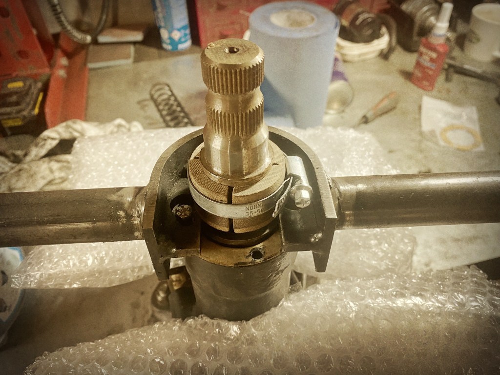
With the appropriate tool and following the Green Bible it all went together quite easily. It is quite nerve wracking compressing the spring when you have to be in the firing line. I am not sure how you could do it without the tool.
The most time consuming part was filling it was EP90, which is thick and slow to get in. I did it without the seal cap in place and filled it to the brim, left it to settle repeatedly over about 1 hour. When installed you need to add oil via one of the crew holes and have another out as vent.
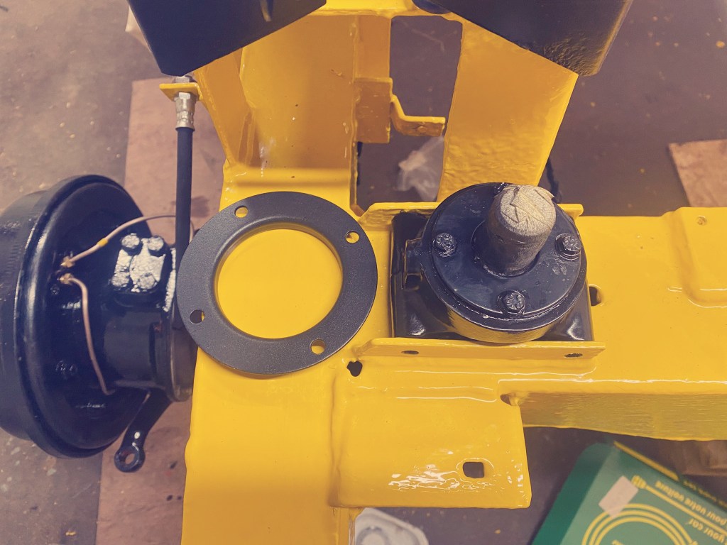
It slotted into the chassis nicely with some grease for good measure, but I hope never to have to remove it again. I left it about a week before bolting it in and adding the retaining plate just to make sure it wasn’t leaking. So far so good.
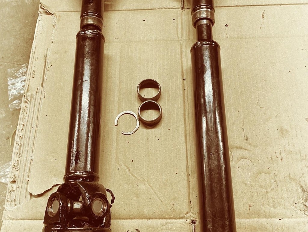
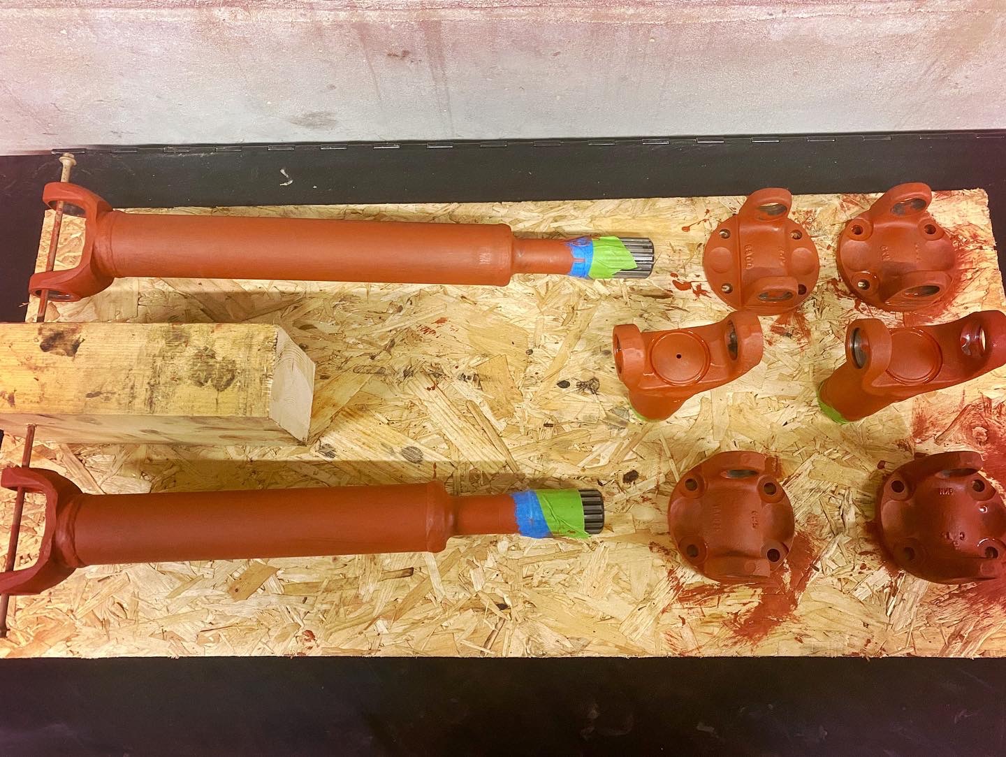
With the prop shafts painted it was time to assemble them. Genuine Parts GKN joints went in a treat and preparation of the circlip grooves paid dividends as they went in easily, with a little copper grease in case they need to come out again. It is pretty satisfying to repair these rather than buy new ones. I still need to fit the felt washers (bought as Norton foot peg gaskets) in the sliding joints, but I think I need another split washer.
Refurbish don’t replace.
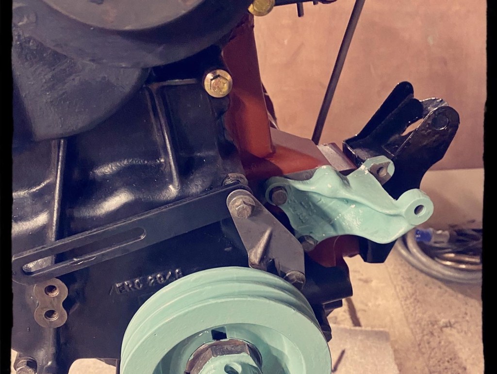
After the saga of getting the pulley on, I realised that I had also managed to correctly get the lower timing pointer bolt in first. The upper is waiting for the missing spacer, but I put the alternator stay and pointer on loosely, and also fit the spiffing alternator bracket. The MOD recon blue is part of the history as 05 KD 28 was clearly converted from a 24V 90A to a 12V variant whilst in service.
Some of the parts are really quite sublime.
I continues with dressing the engine by attaching the carb adaptor, vacuum pipe, heater tap, and rocker cover. A new breather and correct bolt are yet to come, and the coil bracket needs to be fitted. This bracket (which goes between the centre and right rocker cover bolts) is another 24V variant, but it does work quite nicely.
Nearly read for the ball.
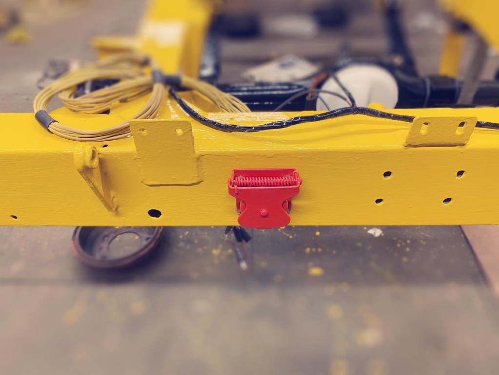
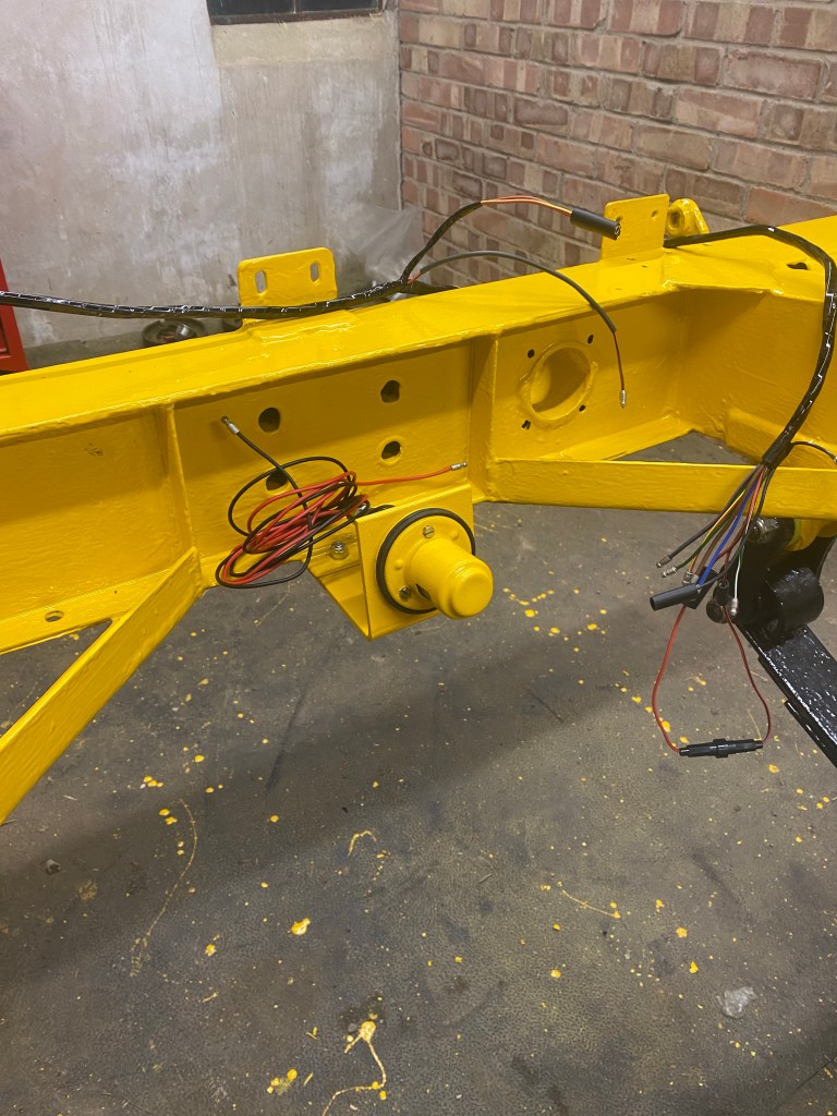
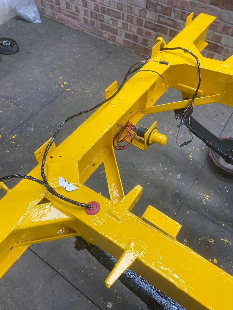
With a little bit of spare time I also managed to fit the Nato trailer socket and cover. It does have a touch of Noddy car when you have the yellow and red together, but I like it.
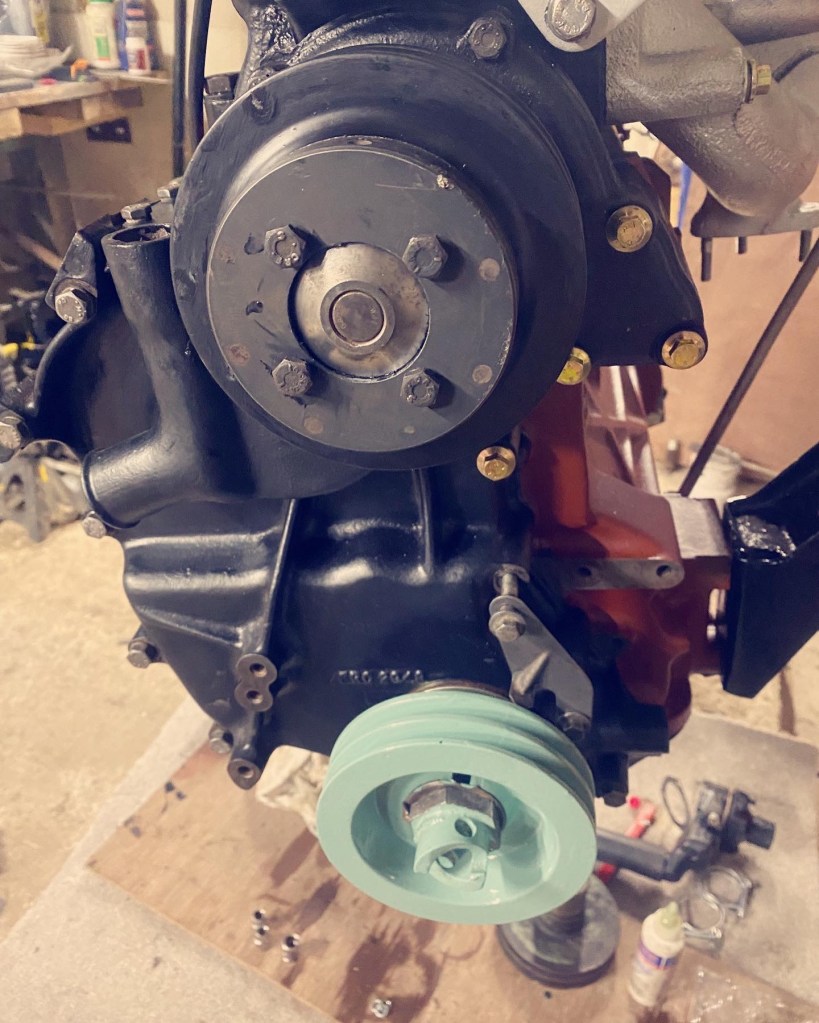
I was aiming to quickly get the crank pulley on and was quite proud that I had actually remembered to put the key in the shaft before putting the timing case on. Needless to say that this quick on turned into a very frustrating deviation into fishing.
As i was gently persuading the pulley onto the shaft I heard a very depressing sound; a little clink as the key fell into the timing case. At this point I realised that it may have been better not to have put the sump on, but that ship had sailed. So what to do? Timing case off? Crankshaft seal out? Sump off? None of these were particularly attractive so in managed to find a magnetic washer, and proceeded to go fishing with this magnet on a length of copper wire. Eventually I caught the key and managed to retrieve it, before embarking of the next challenge of getting it back into the slot.
After getting this pulley on I attacked the easy job of the water pump pulley. Yes I know it needs a touch up.
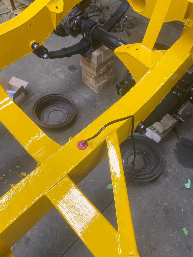
I had taken the wheels off a while back and now it was time to get the brakes back, swivels and hubs up to snuff. The wheels also went back on the road to begin their makeover.
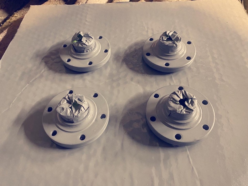
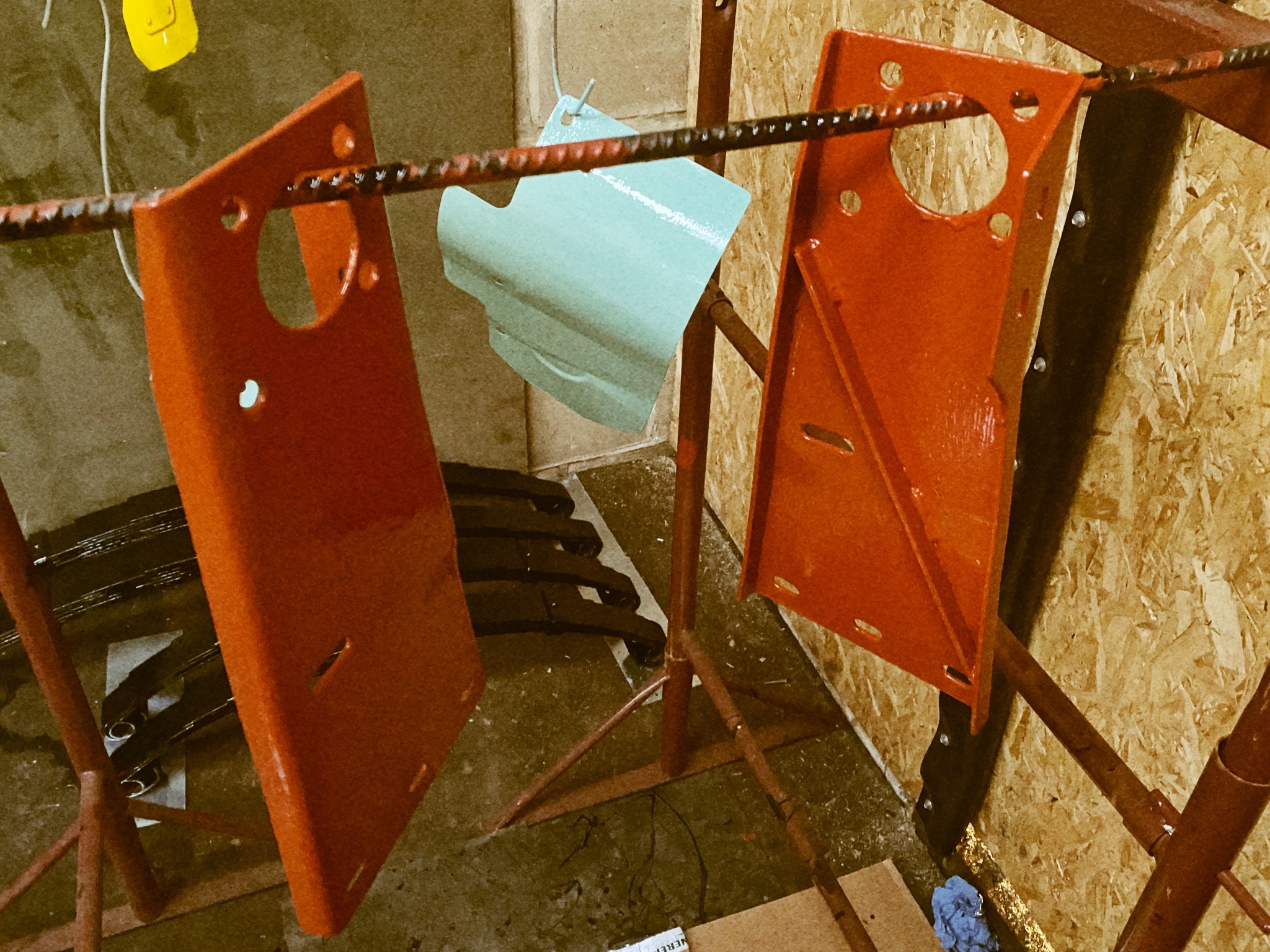
Drive flanges were stripped back and zinc primed before being undercoat in white.
Driving ahead.
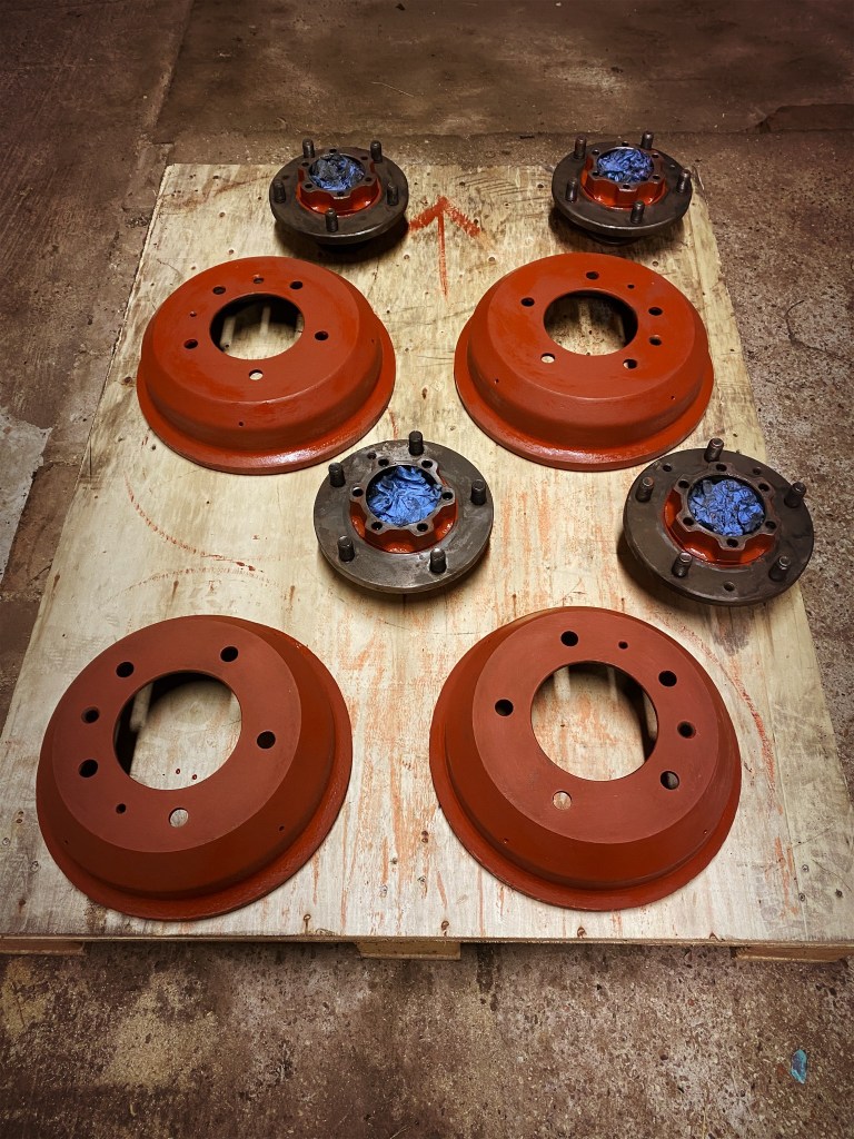
I didn’t actually need to take the hubs off to paint them as I had not long since rebuilt them, but I thought it was easier to do so. It made life easier and i found that one seal must have been slightly out of square as the shoulder holding the spring in place had worn off. I have these in stock as spares so easy enough to do. Once stripped they were red oxide primed and place in the correct orientation with my high-tech arrow to remind me!
Brembo?
Once primed the drums went down the chassis paint line whilst I undercoated the hubs in white before they and the drive flanges joined the ever increasing number of yellow bits.
Join the hub; .
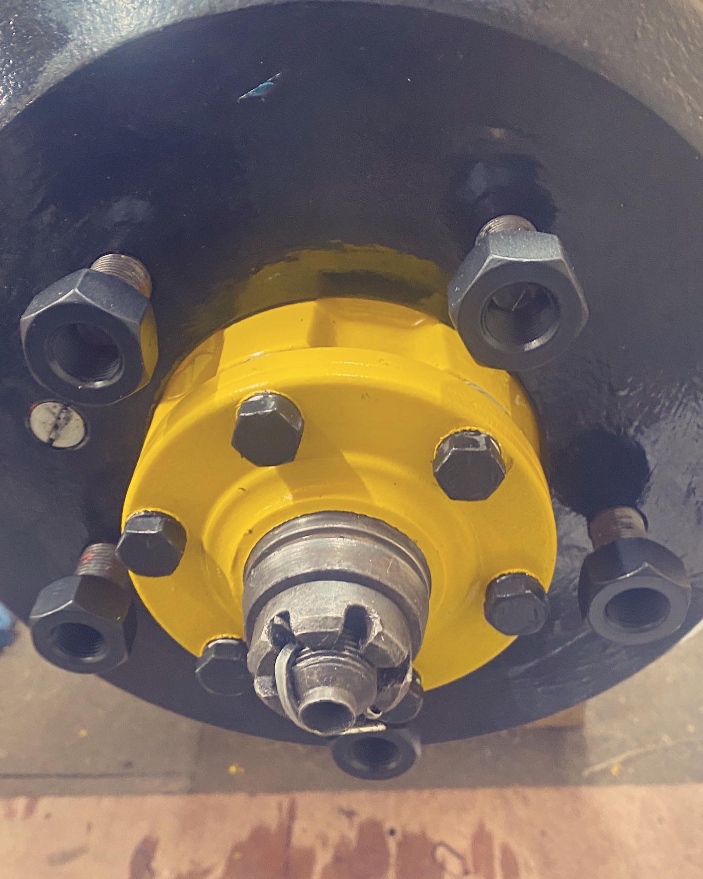
I had also cleaned and spray painted the wheel nuts and drive flange bolts / spring washers. Hammerite seems to work ok for this, and I went for black as I can see that they were either green, black or yellow until some one had fairly recently put a bit of nail varnish on.
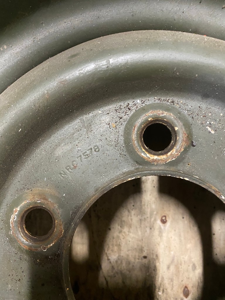
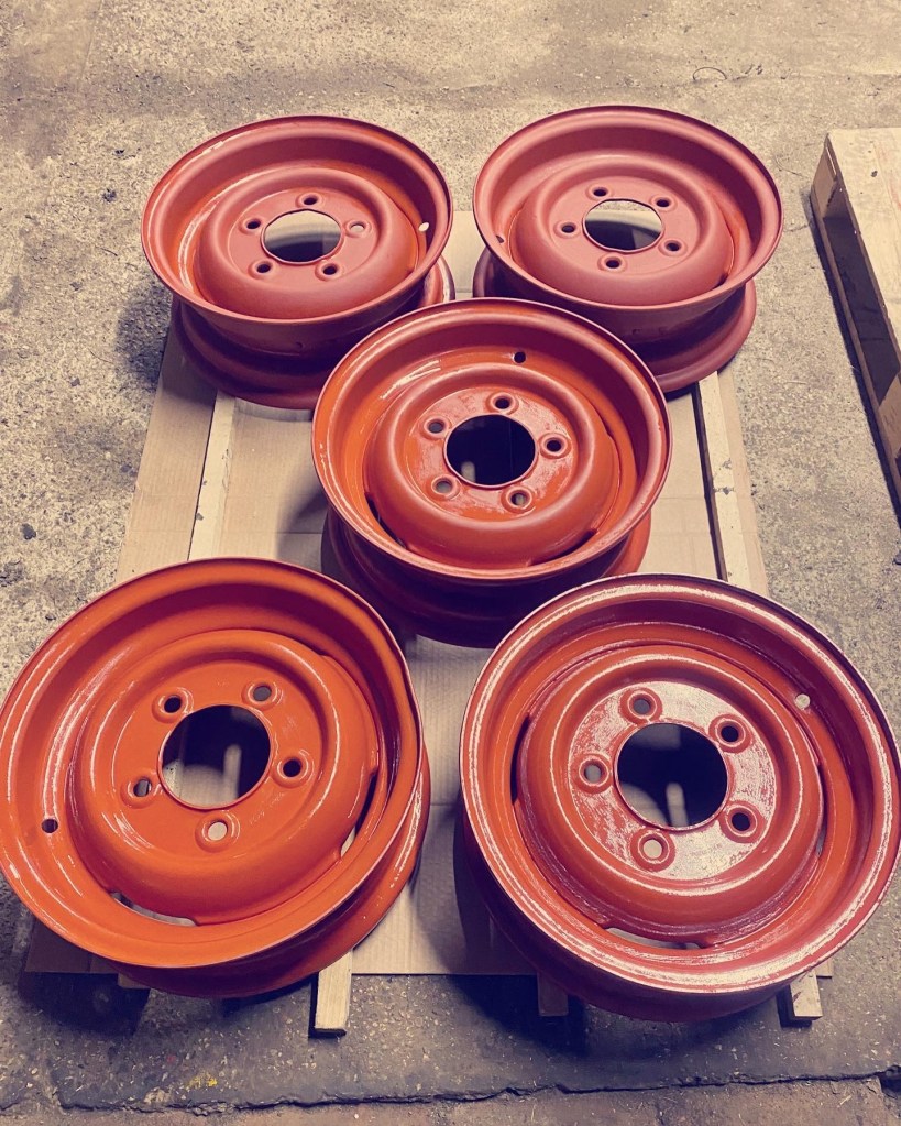
With the hubs now ready to accept the wheels, I turn to their journey. I am sure that they are the original wheels as they appear to have only been white and very badly painted in NATO IR Green. They are NRC 7578 FV 2000727, which is absolutely fine but these are clearly later second hand replacements for what I guess were 5in rims.
I got the tyres / tubes and weights taken off by a local fitter pretty cheaply and then gave them a good look over. One had a pretty noticeable (less so after finessing!) dent in rim edge (top of pile in below pic) so this will be the spare.
I’ve got your number.
Despite the corrosion inside the rim, particularly under the tube near the valve stem hole, they came up a treat with the shot blast. It wasn’t expensive and saved a huge amount of time.
Having a blast.
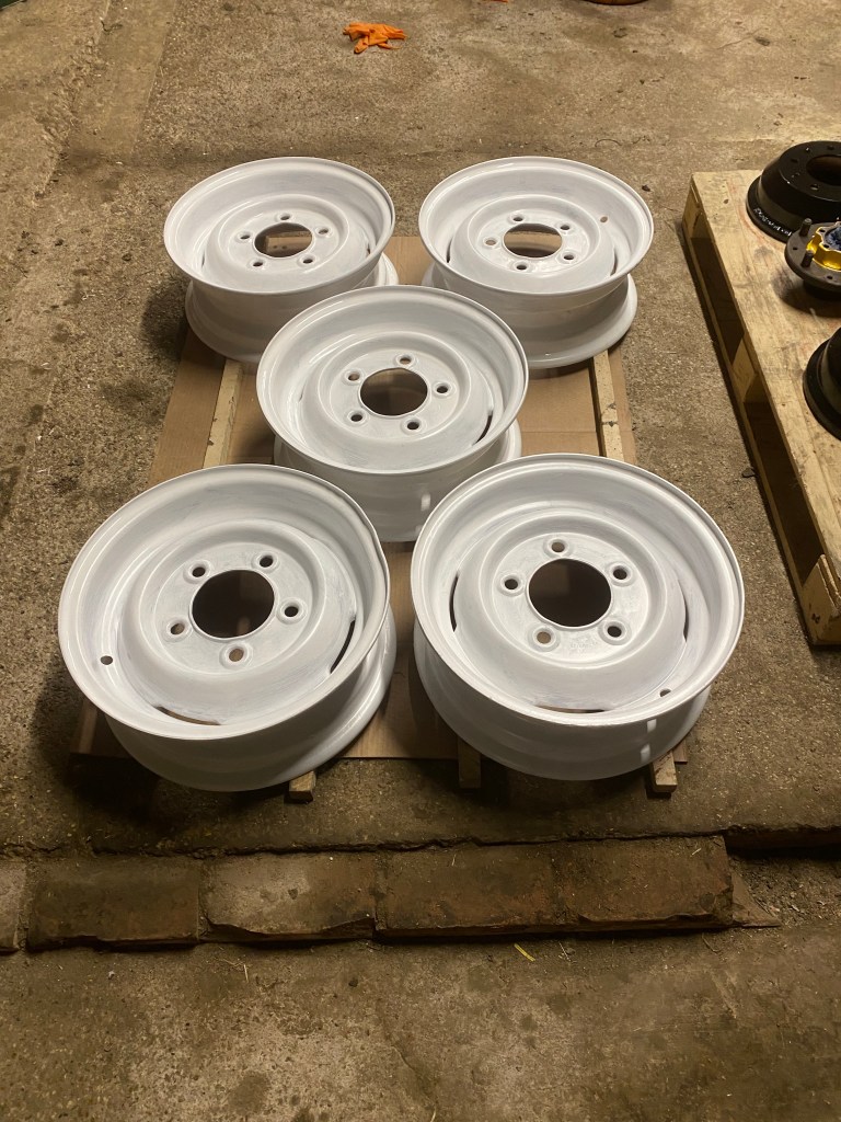
I got the read oxide primer on pretty sharpish as they, like all Land Rover parts, are looking for the next way to rust. This propensity is much like that of sheep to find ways to die and so I then gave them a white coat.
Next stop yellow.
The rims need a bit of flatting and touch up on the undercoat before the yellow starts to go on.
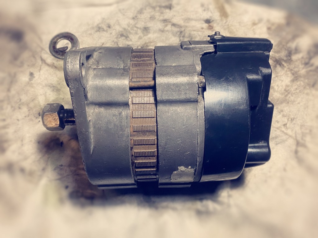
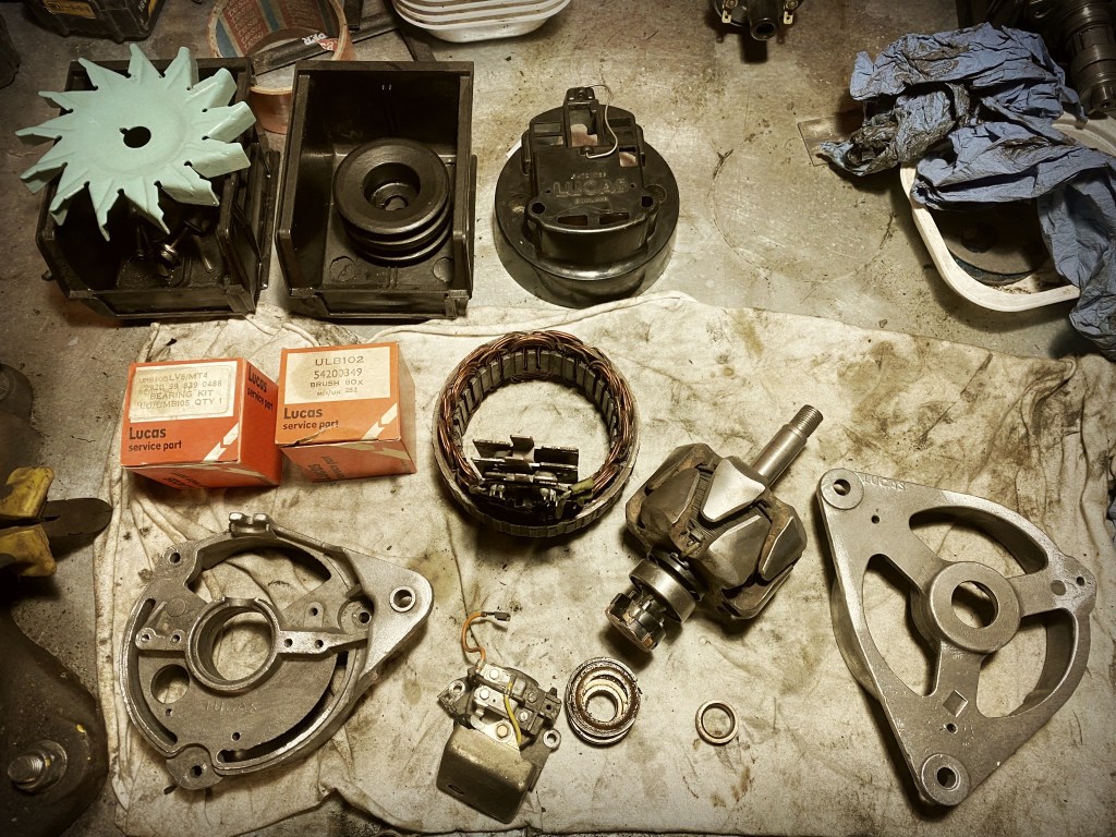
This is a actually a focus on the alternator over a few days and a change of plan. I had started work on the Lucas alternator with the intention of just giving it a good clean and painting the pulley and the fan. Once opened and stripped it didn’t look too bad and the brushes and pickup still had life.
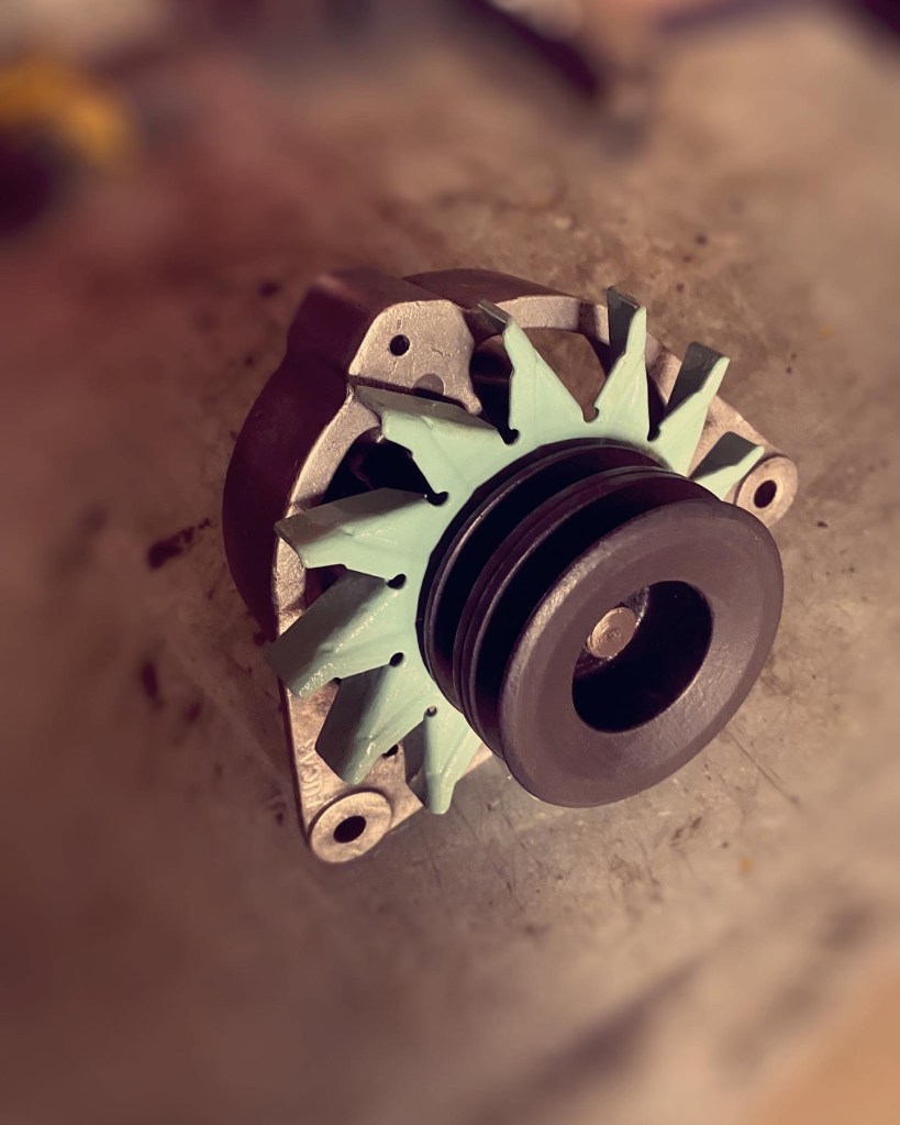
After cleaning I put it all back together and was pretty happy with how it had scrubbed up.
Pretty but …
Whilst I slept, the Alternator, in the words of Arnold Schwarzenegger, said I’ll be back.
Back to square one.
I decided that the front bearing not being 100% was enough of a reason to give it some proper life extension work and so completely strip it it down and replace all the consumables. Luckily most past are readily available as they were installed in one heck of a lot of British cars.
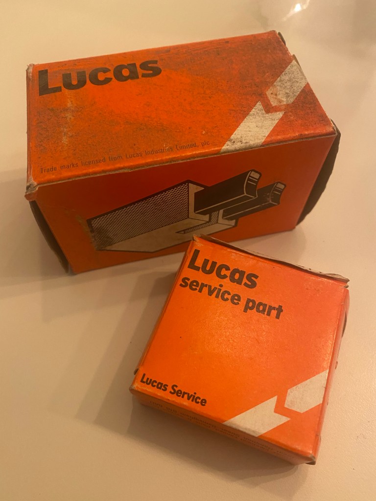
I do love NOS
They also have the advantage of being built to be repaired and not chucked in landfill.
BackFrontFitted
It should be noted that all the parts in MOD recon blue were that colour when I got the vehicle and this all ties in with the change from 24V to 12V that seems to have been in service so I go with age appropriate parts.
If you haven’t seen the 1978 Sam Peckinpah film, you haven’t lived. Quite fittingly this film sprung to mind whilst fitting the convoy light. This was fairly easy although a bit of painting was needed. Yes the leads do need trimming and probably some heat shrink. Ill think about this once I have the trailer socket in place.
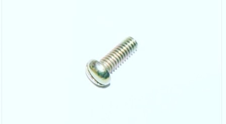
In fact the hardest part of the process was buying the screws which hold the light to the bracket. JLR wouldn’t sell them to me. Craddock did.
The top secret dangerous military component.
You may notice that I have installed the chassis loom. This is the first part of the Autosparks loom and so far so good apart from the grommet they had pre-fitted. This was massively too big but I had already got the correct ones as I wasn’t actually expecting the grommets to come on the loom. These, being smaller, were a right pig to get over the connector at the bullhead end. Top tip: needle nose pliers to stretch them over the block after warming them in hot water.
Rear.Front.
To run the loom through I used a length of thick earth cable and I found it easiest to feed in both directions (fore and aft) from the hole under the chassis rail dog leg. This was then pulled through with the loom taped to it. This would appear to be the simplest part of the wiring!
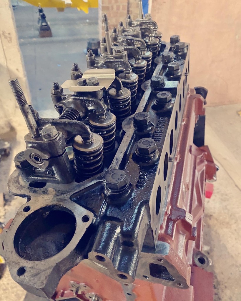
The chassis is now begging to have the engine added and so that means I have had to get back to the engine rebuild. Adding the head is one of those nerve wracking moments, especially as the two cardinal sins of head gasket are both present here. 1) the new Elring gasket doesn’t say ‘top’ so self-doubt creeps in. 2) there are no studs to hold it in place, although i could have made some.
In situ and all the bolts go in
Once loosely placed, the bolts all went in freely (I had cleaned the holes and run a cleaned bolt in earlier) and then I tightened them to first contact. I am an engineer and have quite a lot of experience in why torque is a rubbish measure in bolted connections, but these heads have been working with the LR torque values for a long time. In brief (i have written thousands of words on this subject) you need to check that the bolts are turning by similar amounts for given changes in torque as the turns equal displacement and the displacement gives the tension which is the aim. Here is how I ramped up to torque (65lbf ft) whilst of course following the bolting pattern:
Run bolt to first contact noting if any get harder or easier as you go.
Apply one quarter turn to each with a small ratchet so you can feel, again noting any that are harder or easier. Back off tight ones and retry feeling if improves
Torque to 20lbf ft and if any turn noticeably less return to them in order but torque to 22lbf ft or the degree of rotation if that comes first. This should only small differences.
repeat with all to 40lbf ft and then 44lbf ft or rotation which ever comes first.
Torque to 60lbf ft
Torque to 65lbf ft
To an extent you need to ‘feel’ it rather than just relying on numbers
All torqued and ready to go.
You may notice in the above I have fitted the baffle to the rocker shaft, This was missing before, but would seem like a good idea given it sits directly below the breather when the cover is on.
Now it was time to attack the timing. This is another job that fills you with dread. First step was to fit the cam shaft retainer and then the second is to ensure all pistons are at mid stroke whilst you position the cam shaft.
Cam shaft locked and key in.
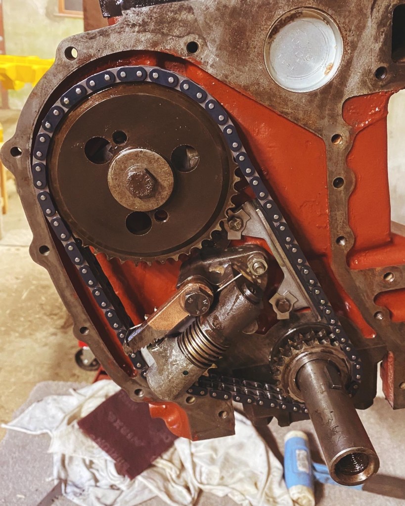
Then the cam shaft chain wheel added and then it cam be rotated to aligned the mark with the 11 O’clock bolt hole.
Cam timed
Next the engine can be turned to put cylinder 1 at tdc. You can feel this and check from underside. The keyway should be vertical to the engine (perpendicular to plane of head). I also installed the damper loosely as this helps support the chain as you place it. The old damper had to go as it has seen some action which suggests the old chain was becoming stretched and slack thus rubbing on the damper.
New damper and tab washers.
Next was the small task of putting on the chain which is simple enough, but care needed to ensure nothing moves. With that the tensioner could be installed, which is a bit fiddly as it wants to push out the whole time. With the tensioner in place the damper could be set a thou off the chain and tab washers locked.
Note that the pulley key is in place!
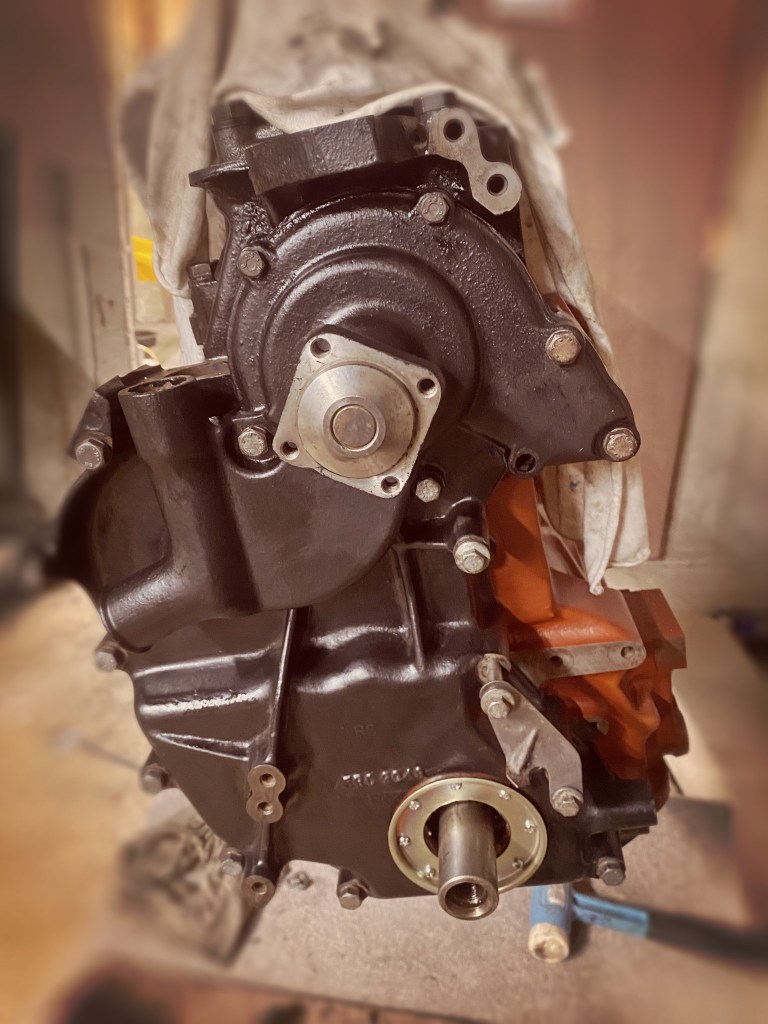
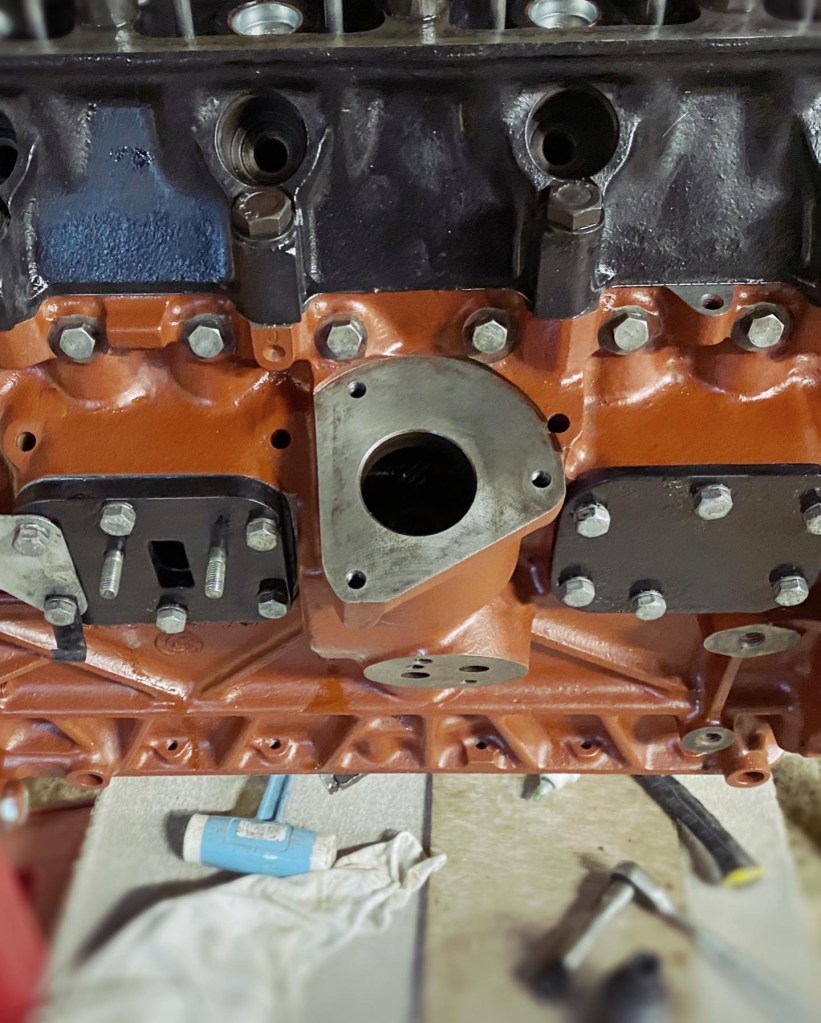
putting the case on is pretty straight forward, gasket and smears of hylomar, but care needed to get right bolt in right place. I realised that a spacer for the timing marker was missing so one bolt yet to be tightened but this also holds the alternator arm. The same drill is needed with the water pump, which also completes the bolting of the timing case. I decide to change the bolts for the newer flanged ones which is why one is missing in the first image below. The second shows the effect although the 5/16 x 1 in unc bolts into the timing case are yet to be replaced.
I hope I haven’t forgotten anything!Metric marvels.
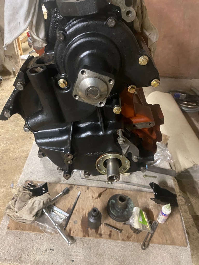
Final job of this phase was to fit the forward and fuel pump plates and the pump itself, not forgetting the brackets also fitted to the rear plate. The lower centre bolt should have a P clip on it for wiring, this had been cut by someone before and so ill add it once I know exactly what goes where.
Plates on.Pump on.
You may notice that the pump is not the original one. The late Delco pump had crimped valves inside so I couldn’t overhaul it. I went for this ‘Pride’ one as being E10 compatible even though I’ll only use E5 (depending on how prices go!).
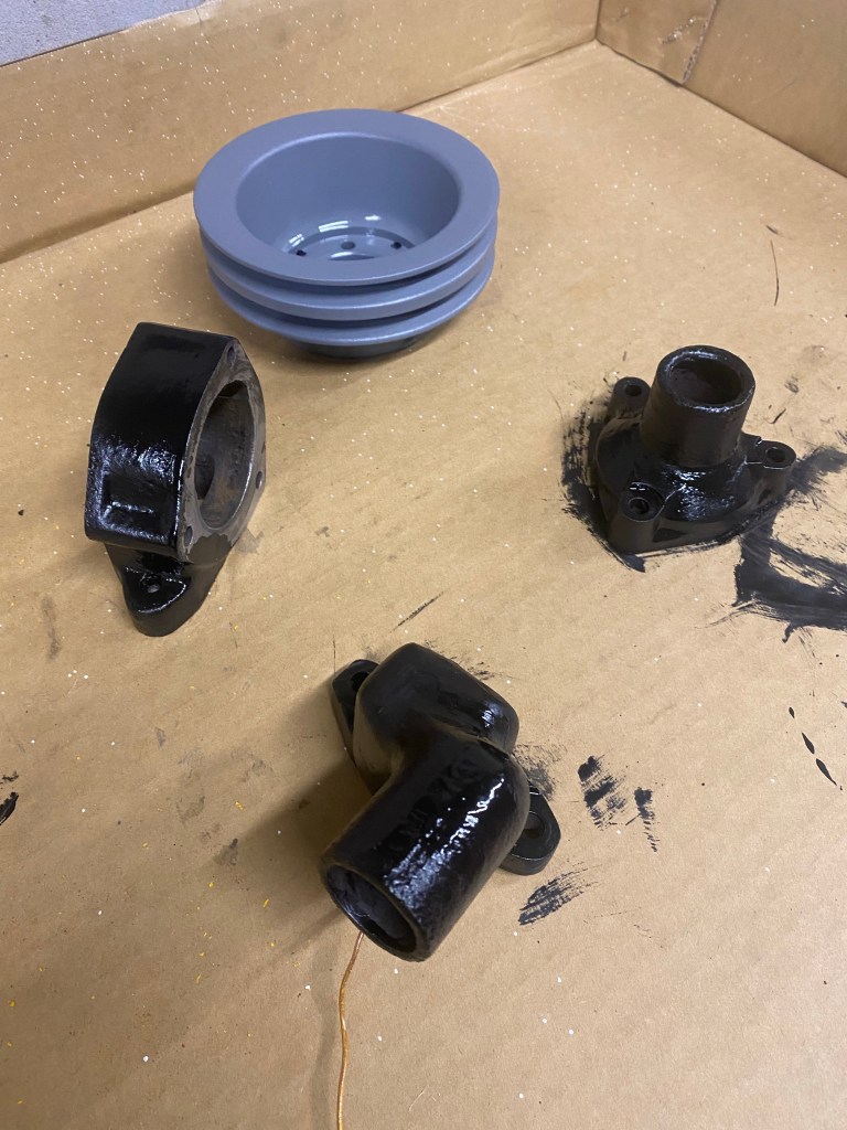
As I build the engine up I am also painting the bits as I need them. Crank pulley returned to the MOD recon blue (which maybe related to the suspected change from 24V to 12v) as is the alternator bracket.
After market but closer to original (cracked) than genuine part.
Thermostat housing and fan pulley are all going to be black – the fan pulley is lagging behind as I had forgotten it! Soon Ill be able to get it back together, but first I need to decide what to do with thermostat – the current one is 88 deg C.
Before getting round to making the chassis roll once more, I cleaned up the check-straps. These are part of the select band of parts to have been brought into the house to be soaked and scrubbed. I am somewhat tickled by the Hi-Speed reference, but the Dunlop yellow looks good and is period appropriate.
Check, 1, 2.
After bolting on the bump stops, and adding the check straps (half only) I put the rear axle in with a little more ease than the front despite the increased weight of the springs. I promptly made the chassis roll free again! I have chocked it up so it is sitting on the U-bolts ends rather than on any paint. This allowed the wheels to come off and the brakes to be opened up once more. This will allow painting of the hubs and a check that they are in fine fettle. The springs need to compress a bit to let me get the check straps fully on and to install the dampers. Hopefully the weight of the engine will achieve that. With that I let the chassis do the talking .
The last few days have largely been taken with painting, and in some cases the repainting, of bits that I need to keep moving forward. However, I did manage to get the front axle in which is a major milestone, but has led to some more painting being needed!
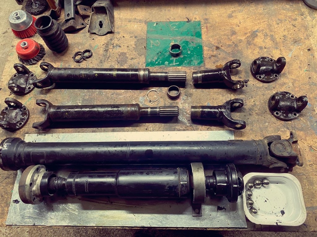
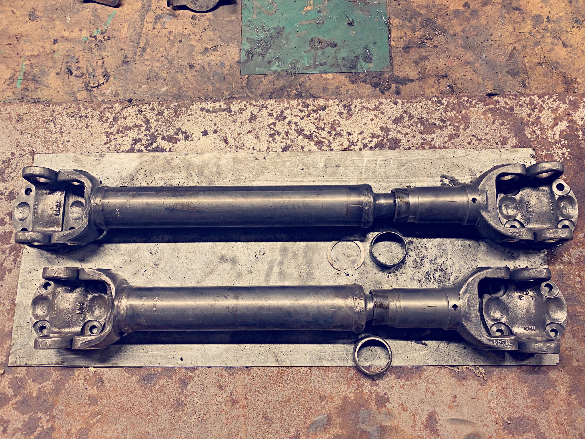
I do tend to flit between jobs to have a change of pace and so decided that as I was getting towards needing to fit the propshafts I would add those to the painting pile. First step was to strip them down. This involved a fair amount of press action and some choice persuassion. The hardest caps to remove were the from the front to the differential. It seems the shaft had rubbed on the saddle so slightly deformed the eyes. It does suggest it wasn’t turning well!
Three shafts
You may wonder why there are three shafts; my D4 decided it was time for a new centre bearing. This is a slightly more complex propshaft.
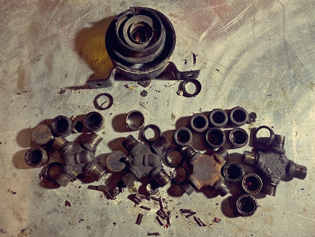
Universal scrap.
You may note from the above that one joint (second from right)is a slightly different size and it doesnt have a grease nipple. The other three are GKN so may be original. Needless to say I am replacing with Genuine Parts.
Mark 1 Propshaft painting tool
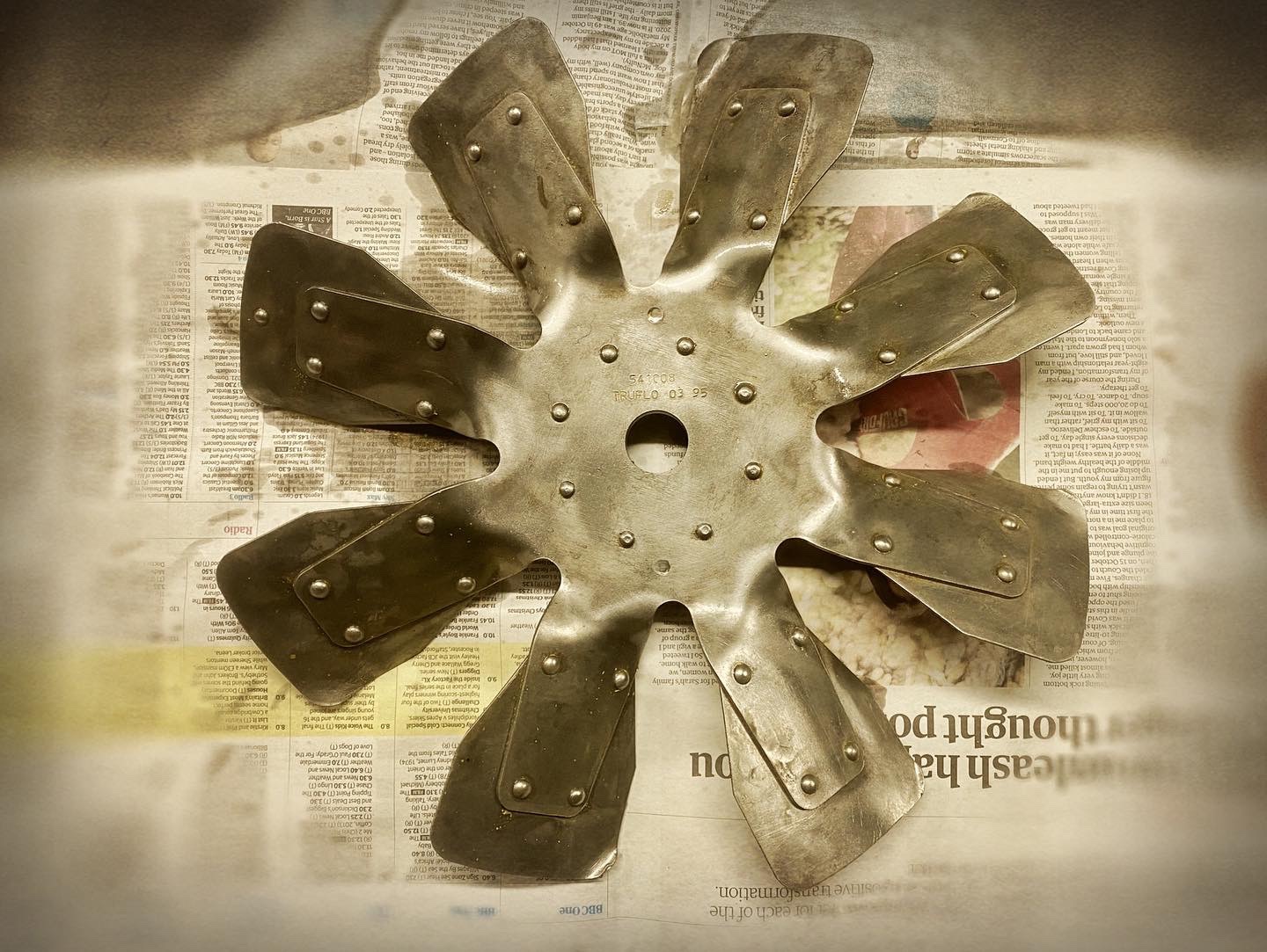
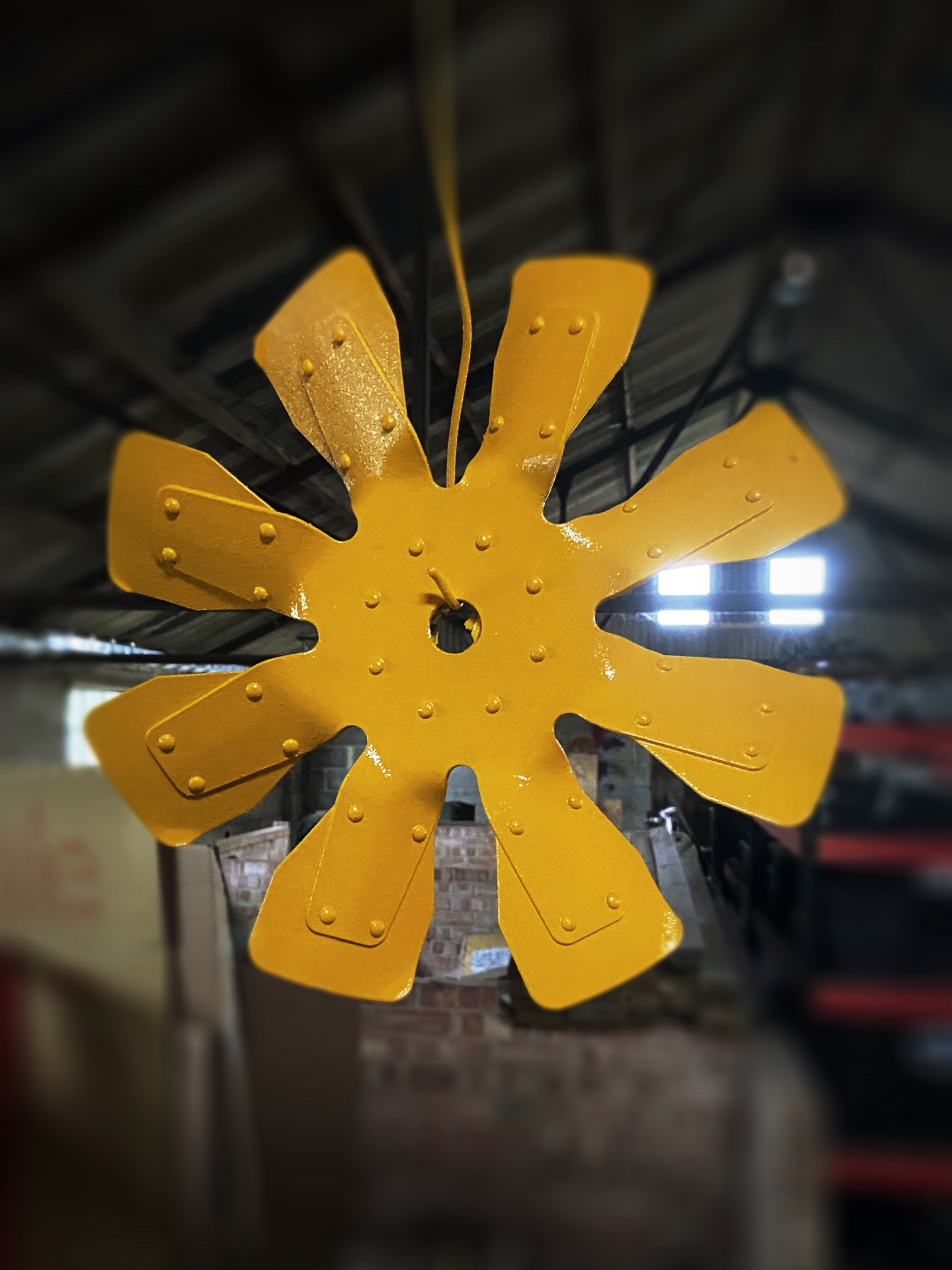
I had tried just to touch up the paint on the fan, but quickly decided I wasn’t happy with it. The solution was to strip it to bare metal (fiddly) then zinc prime, white undercoat and repaint. It now looks much better. The military fan is a thing of beauty.
Sunflower!
After a long stretch of painting I had a change of pace and put the front axle in. This is relatively straight forward, bolt springs on and roll under chassis, but lining up the four ends of the springs can be annoying. Inevitably there was some damage to the paint in the process but noting major.
It is good to reassemble.
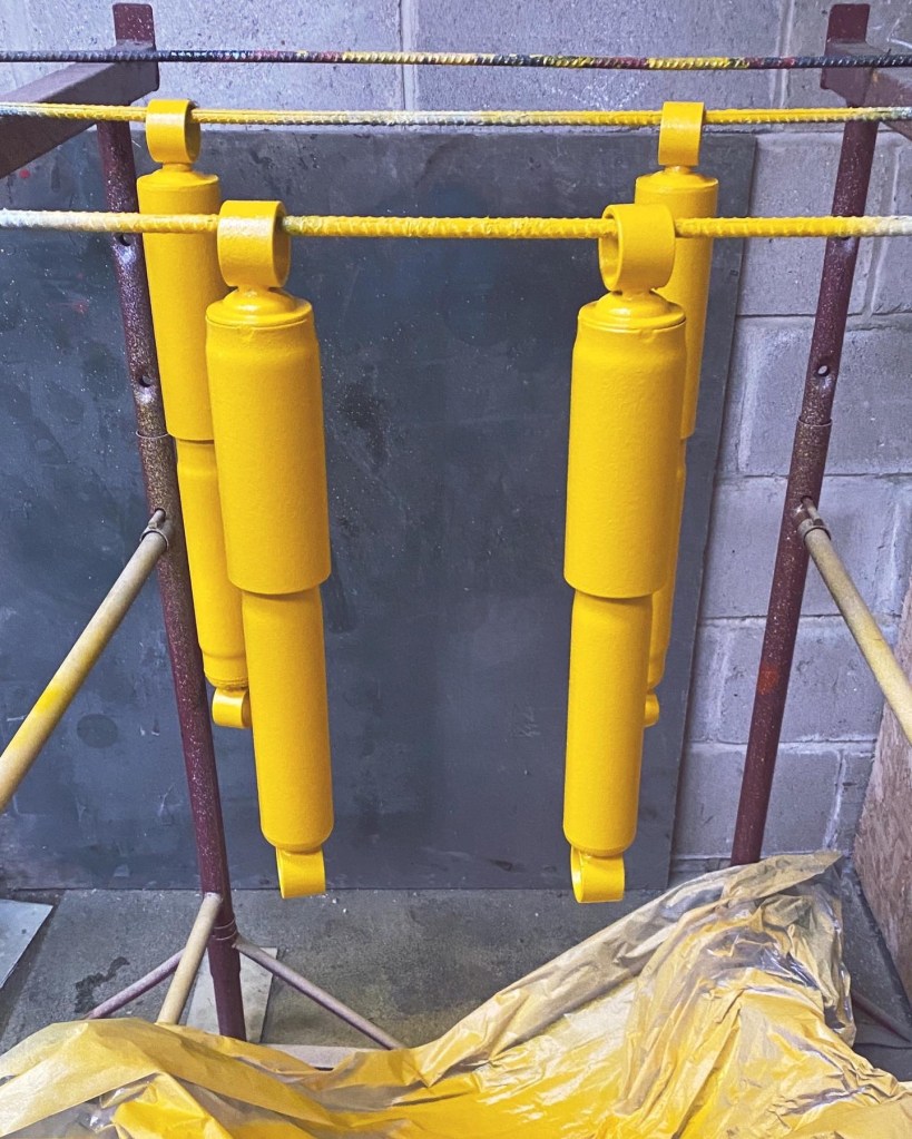
After getting the front axle in I thought I would have a look at the dampers. These were grey (front Girling) and black (rear OEM) and clearly that just wouldn’t do so ….
Now they look light Britpart ones. doh!
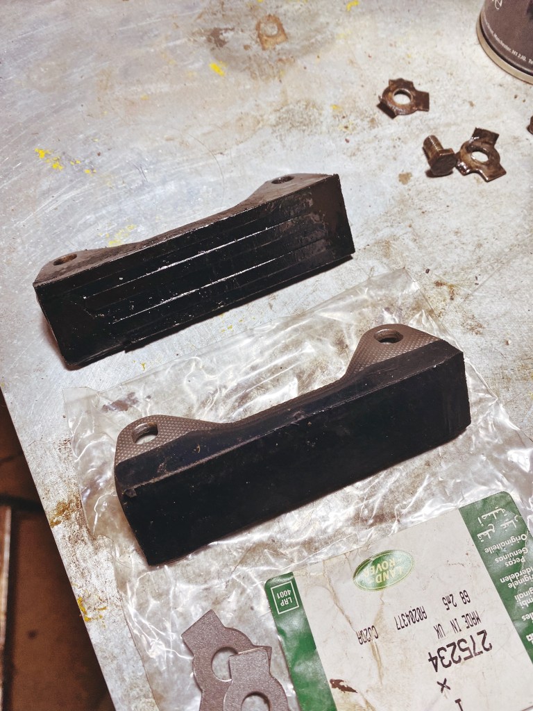
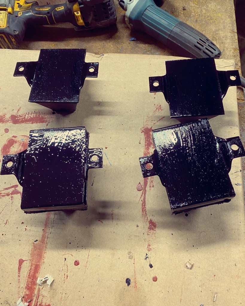
Next items to be painted were the bump stops. Now on this front the parts books list identical ones all round, but the fronts were extended ones. I understand these are correct for early lightweights, but as mine had them I decided to replace them with these once I had found the part number and tracked them down. The rears are standard.
Lower pair are extended fronts. Hopefully this coating will outlast original.
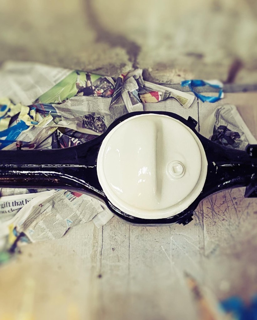
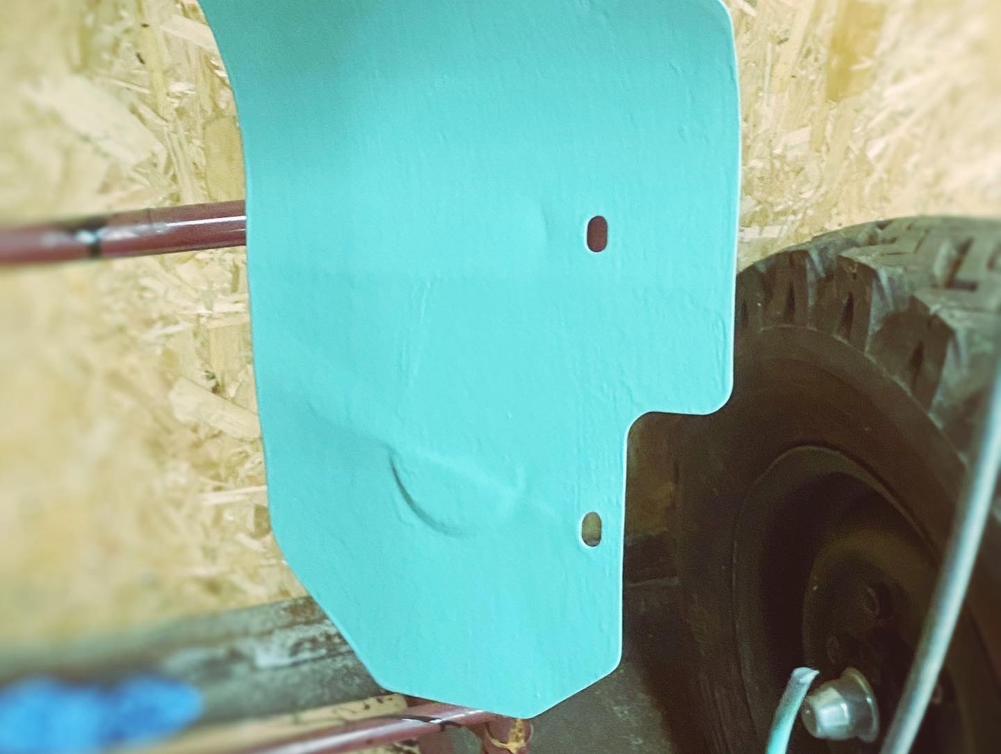
With the chassis waiting to roll the last step was to paint the rear differential pan for the convoy light to shine upon. In the end I stripped the pan down and started afresh rather than adding layer upon layer of paint. It does look good!
I have made progress over the last few days, and the engine is moving towards the meeting of head and block.
I received the new three groove valves and collets and after a bit of trail and error on relative positions had them all in and lapped with good clearances. I now have an unused set for someone with a an early engine! I put the rocker shaft in place pending receipt of new bolts and the oil baffle. This is a part that was missing but seems to be right so …
Rocking!
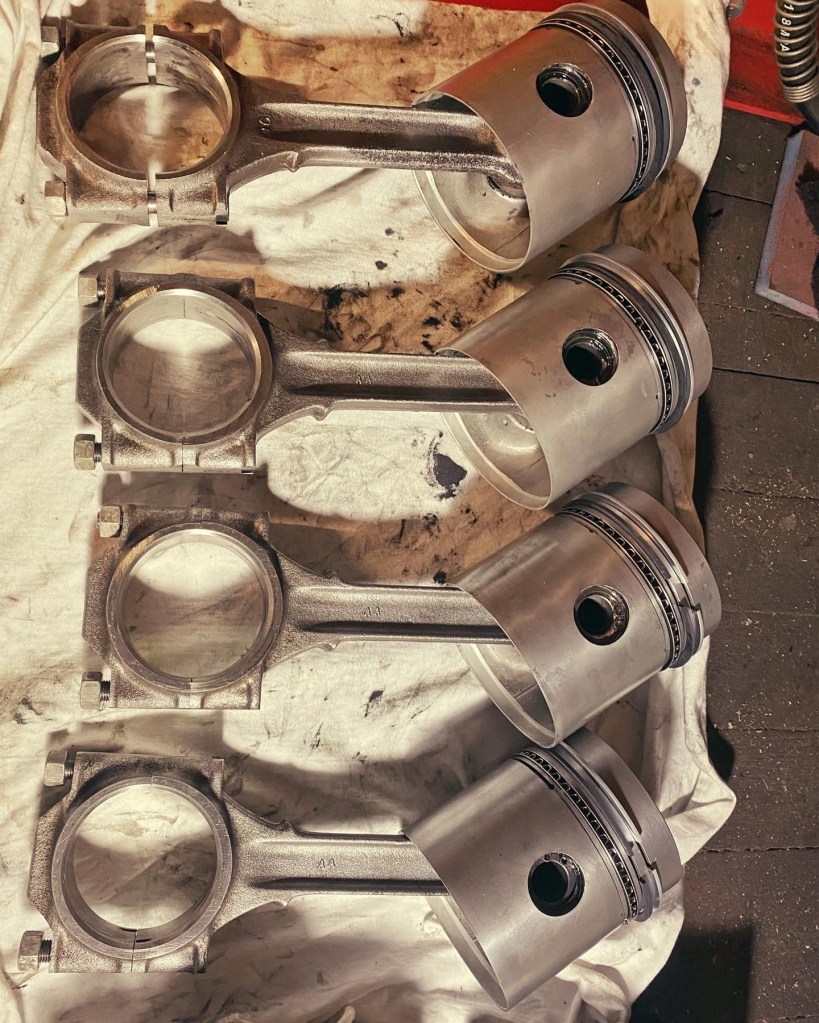
The pistons were still waiting patiently for rings. I had got some Hastings rings which have a waffle with two oil control rings where others have the H profile ring with spring behind. I had been waiting for AE rings but they seem to be completely unobtainable. I was staying clear of Britpart / Bearmach / Allmakes.
Ready to rock.
With the rings on the pistons there was only one place for the pistons to go. With new big end bearings and a piston ring compressor they went in relatively easily but reassuringly tightly! If that makes any sense. I will do a compression and leak down test once assembled just to bench mark the engine.
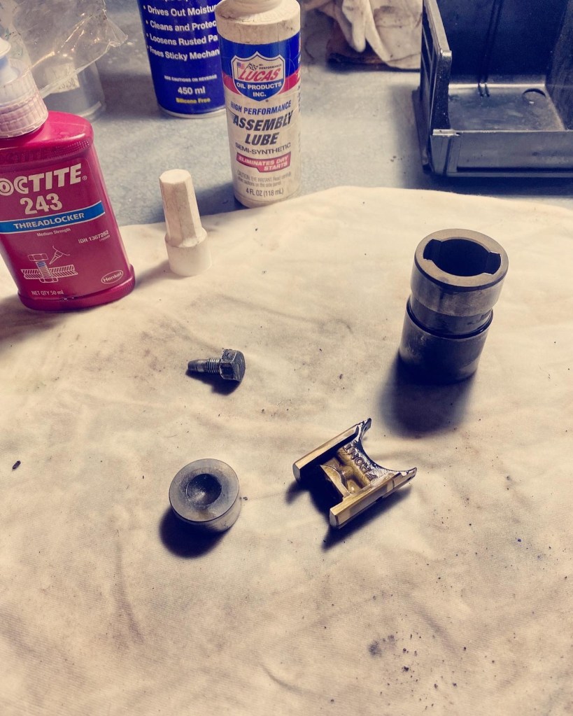
With the pistons in I reinstalled the oil pump, can shaft and skew gear complete with the hidden locating screw. It is a little bit of a faff to line it up but done with long nose pliers. The screw is locked with Loctite 243.
Shame it will be hidden.
With the cam shaft in I thought I might as well put the followers in. This is a somewhat repetitive task! Cleaning, lubing, assembling making sure front remains forward and then Loctite on the locating screws as they are not wired on later engines such as this.
2, 4, 6, 8. Awaiting head.
Alongside this I have been painting. There is so much painting!
Not to mention the cam case covers, engine mounts ….
I am determined to get the chassis rolling now but I am still waiting on u bolts for the rear axle, and I need to paint the drive members.