The chassis is now begging to have the engine added and so that means I have had to get back to the engine rebuild. Adding the head is one of those nerve wracking moments, especially as the two cardinal sins of head gasket are both present here. 1) the new Elring gasket doesn’t say ‘top’ so self-doubt creeps in. 2) there are no studs to hold it in place, although i could have made some.

Once loosely placed, the bolts all went in freely (I had cleaned the holes and run a cleaned bolt in earlier) and then I tightened them to first contact. I am an engineer and have quite a lot of experience in why torque is a rubbish measure in bolted connections, but these heads have been working with the LR torque values for a long time. In brief (i have written thousands of words on this subject) you need to check that the bolts are turning by similar amounts for given changes in torque as the turns equal displacement and the displacement gives the tension which is the aim. Here is how I ramped up to torque (65lbf ft) whilst of course following the bolting pattern:
- Run bolt to first contact noting if any get harder or easier as you go.
- Apply one quarter turn to each with a small ratchet so you can feel, again noting any that are harder or easier. Back off tight ones and retry feeling if improves
- Torque to 20lbf ft and if any turn noticeably less return to them in order but torque to 22lbf ft or the degree of rotation if that comes first. This should only small differences.
- repeat with all to 40lbf ft and then 44lbf ft or rotation which ever comes first.
- Torque to 60lbf ft
- Torque to 65lbf ft
- To an extent you need to ‘feel’ it rather than just relying on numbers
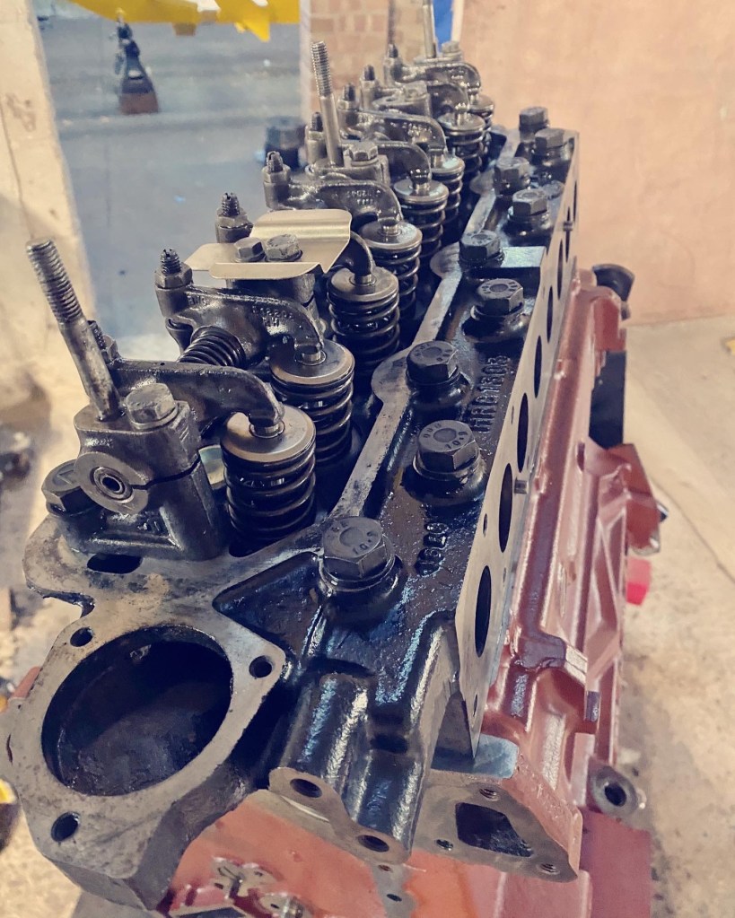
You may notice in the above I have fitted the baffle to the rocker shaft, This was missing before, but would seem like a good idea given it sits directly below the breather when the cover is on.
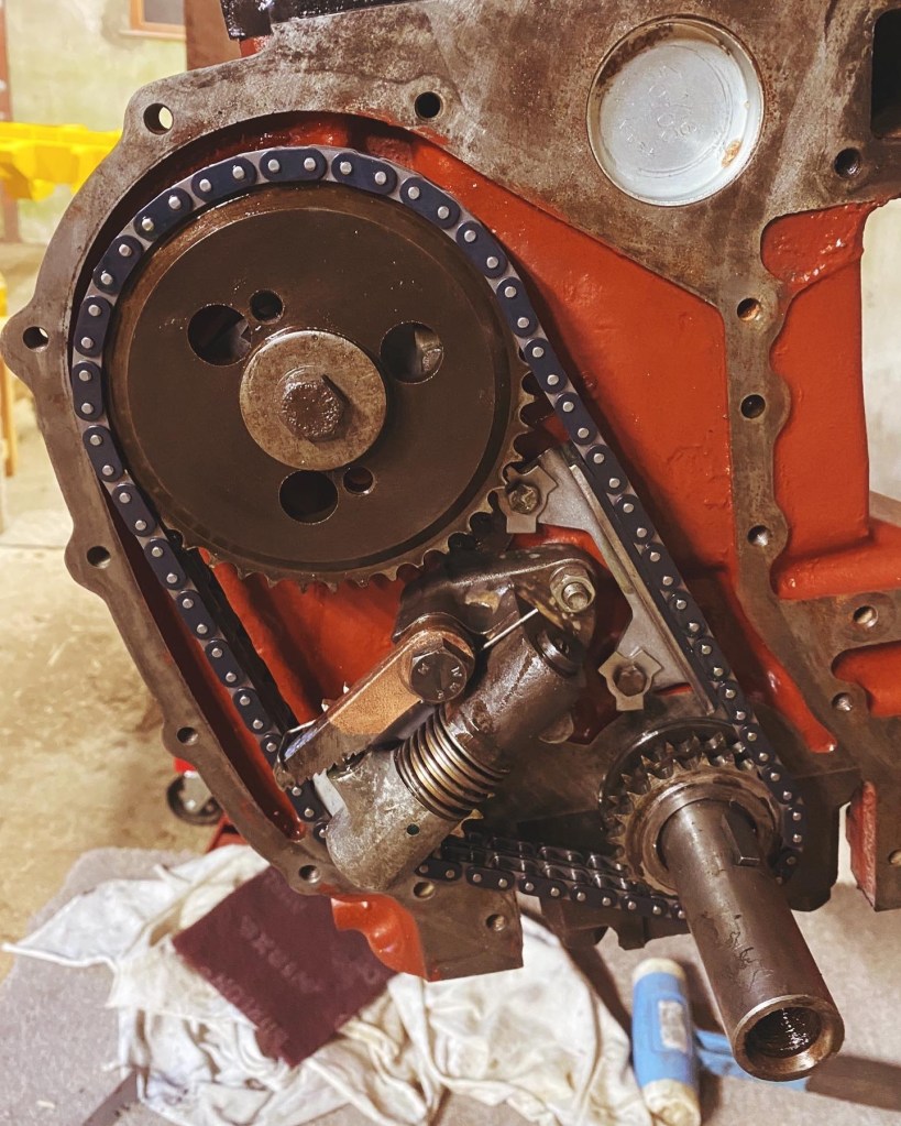
Now it was time to attack the timing. This is another job that fills you with dread. First step was to fit the cam shaft retainer and then the second is to ensure all pistons are at mid stroke whilst you position the cam shaft.

Then the cam shaft chain wheel added and then it cam be rotated to aligned the mark with the 11 O’clock bolt hole.

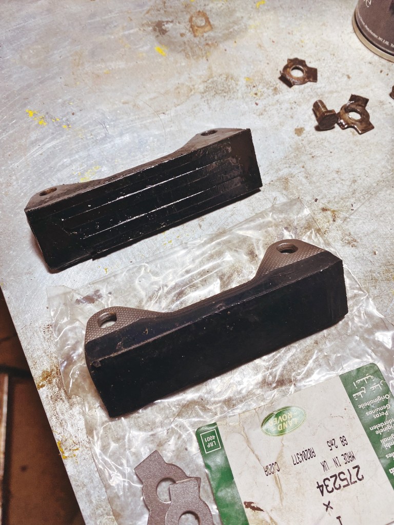
Next the engine can be turned to put cylinder 1 at tdc. You can feel this and check from underside. The keyway should be vertical to the engine (perpendicular to plane of head). I also installed the damper loosely as this helps support the chain as you place it. The old damper had to go as it has seen some action which suggests the old chain was becoming stretched and slack thus rubbing on the damper.
Next was the small task of putting on the chain which is simple enough, but care needed to ensure nothing moves. With that the tensioner could be installed, which is a bit fiddly as it wants to push out the whole time. With the tensioner in place the damper could be set a thou off the chain and tab washers locked.
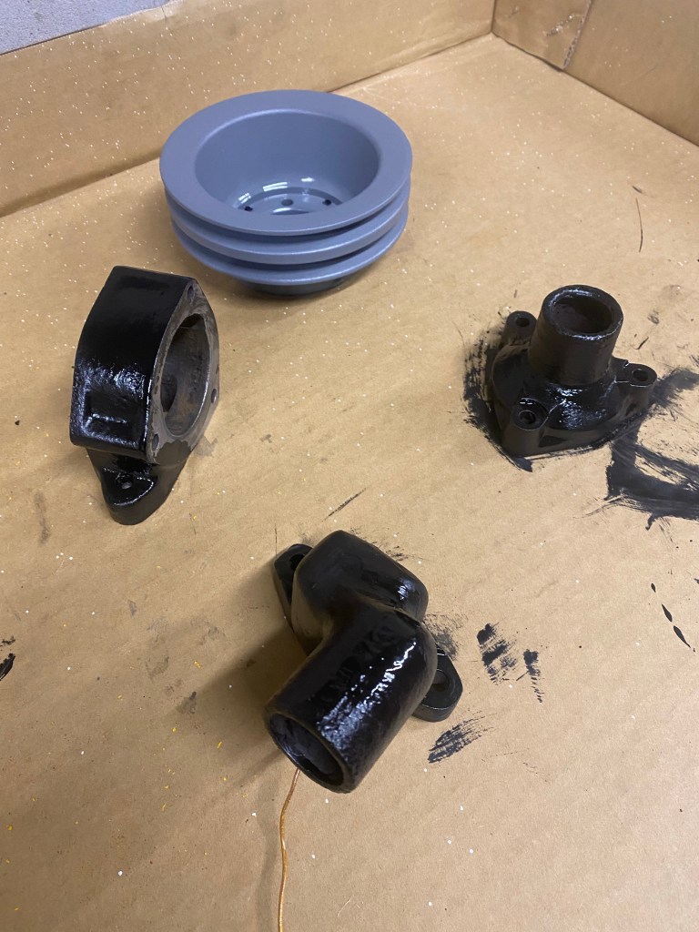
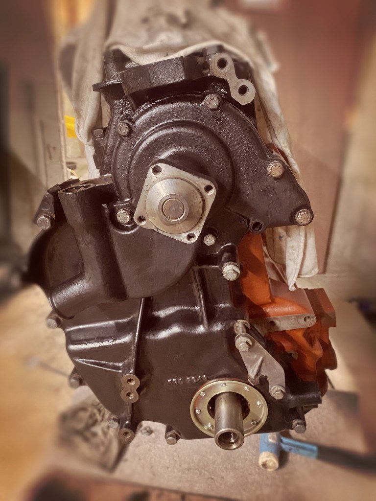
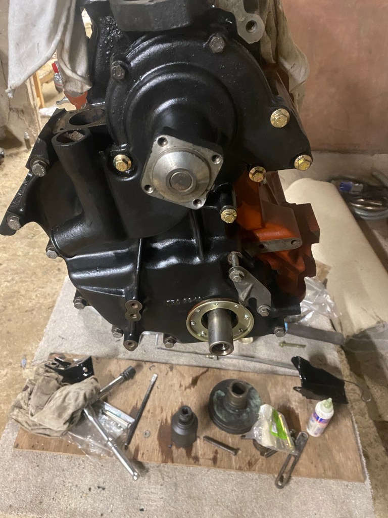
putting the case on is pretty straight forward, gasket and smears of hylomar, but care needed to get right bolt in right place. I realised that a spacer for the timing marker was missing so one bolt yet to be tightened but this also holds the alternator arm. The same drill is needed with the water pump, which also completes the bolting of the timing case. I decide to change the bolts for the newer flanged ones which is why one is missing in the first image below. The second shows the effect although the 5/16 x 1 in unc bolts into the timing case are yet to be replaced.
Final job of this phase was to fit the forward and fuel pump plates and the pump itself, not forgetting the brackets also fitted to the rear plate. The lower centre bolt should have a P clip on it for wiring, this had been cut by someone before and so ill add it once I know exactly what goes where.
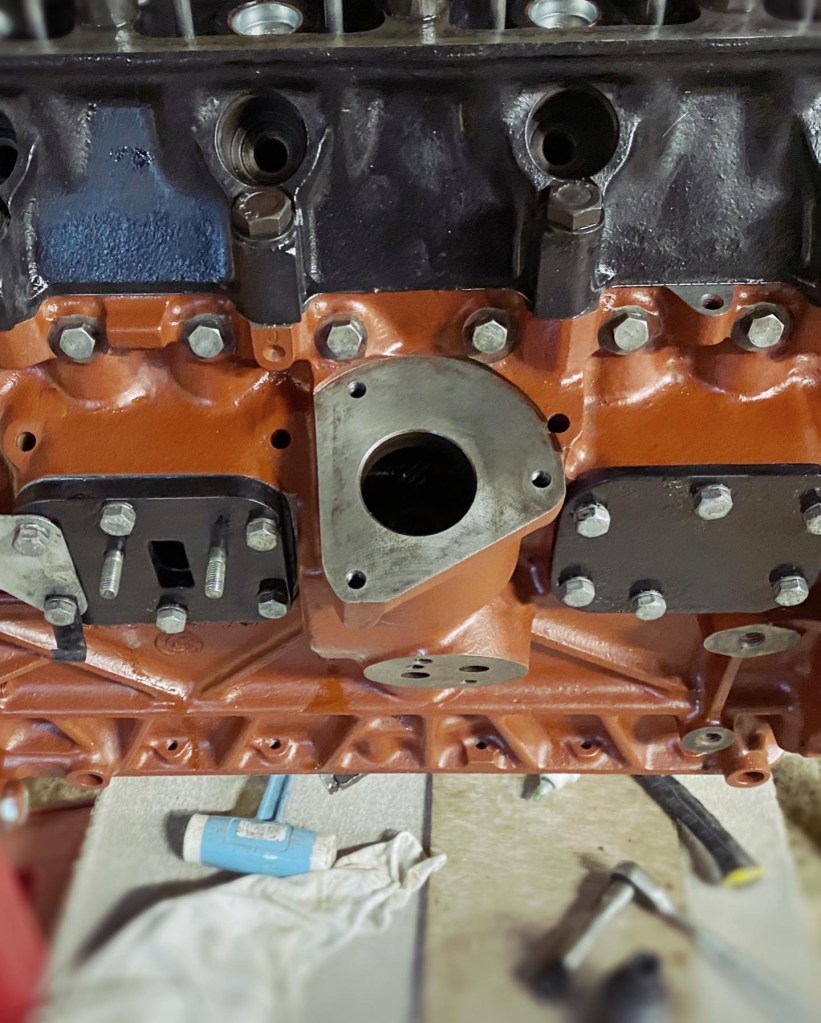

You may notice that the pump is not the original one. The late Delco pump had crimped valves inside so I couldn’t overhaul it. I went for this ‘Pride’ one as being E10 compatible even though I’ll only use E5 (depending on how prices go!).
As I build the engine up I am also painting the bits as I need them. Crank pulley returned to the MOD recon blue (which maybe related to the suspected change from 24V to 12v) as is the alternator bracket.

Thermostat housing and fan pulley are all going to be black – the fan pulley is lagging behind as I had forgotten it! Soon Ill be able to get it back together, but first I need to decide what to do with thermostat – the current one is 88 deg C.